
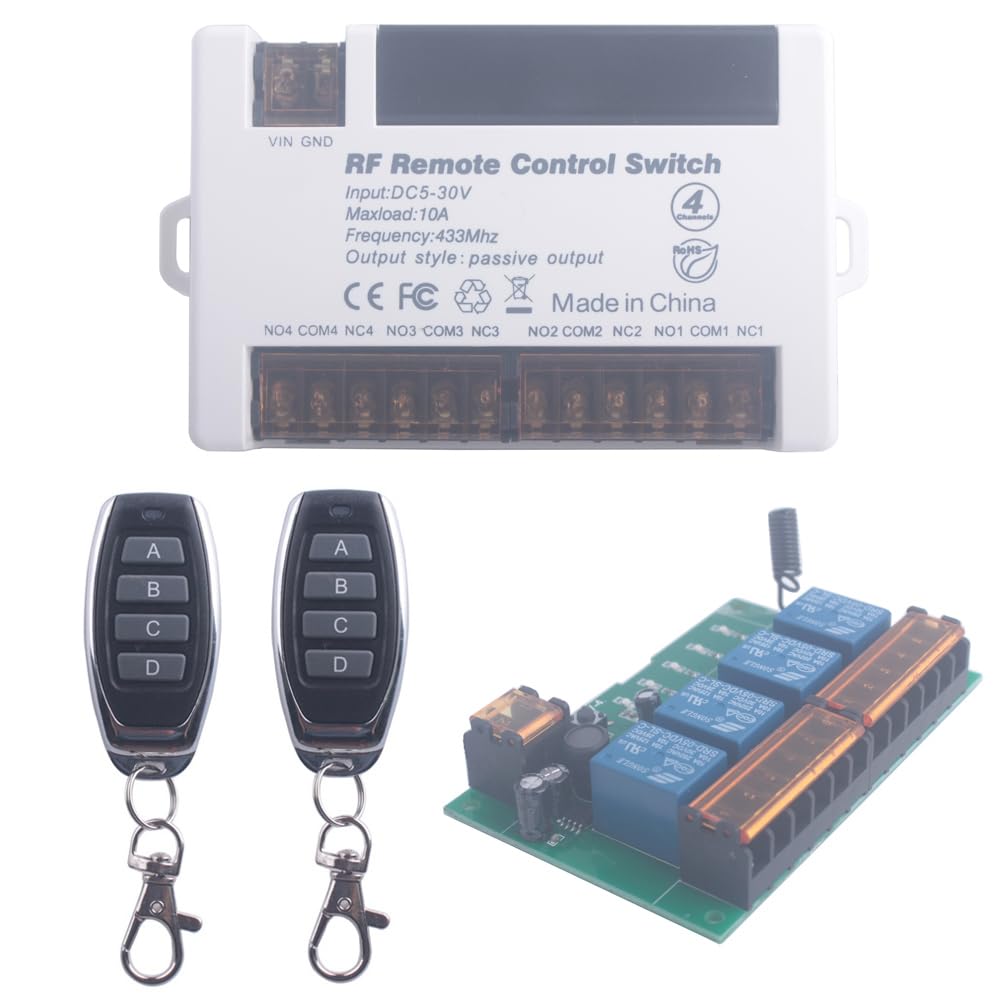
12V 24V 4 Channels Wireless Relay Remote Control Switch, RF 433Mhz DC 5V-30V Garage Door Opener Wireless Switch with Receiver 2 Transmitters, Easy to Terminal Wiring (4CH 2* Controller 433Mhz)
$ 7.23
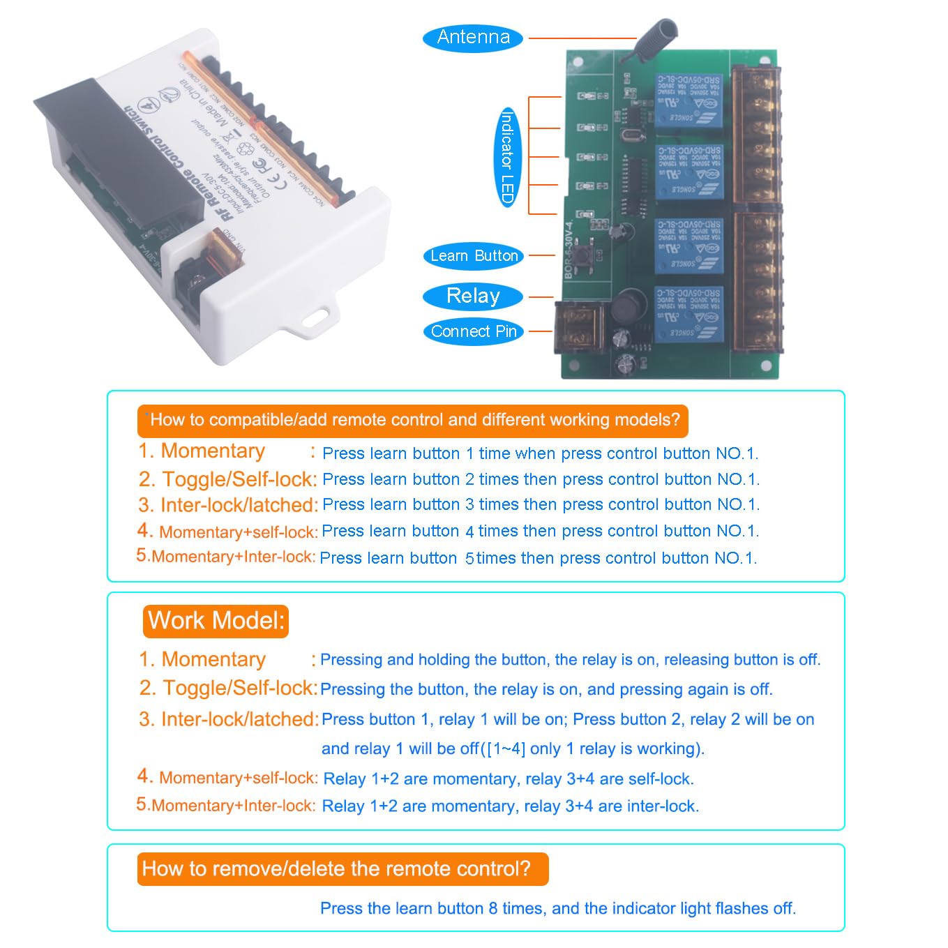
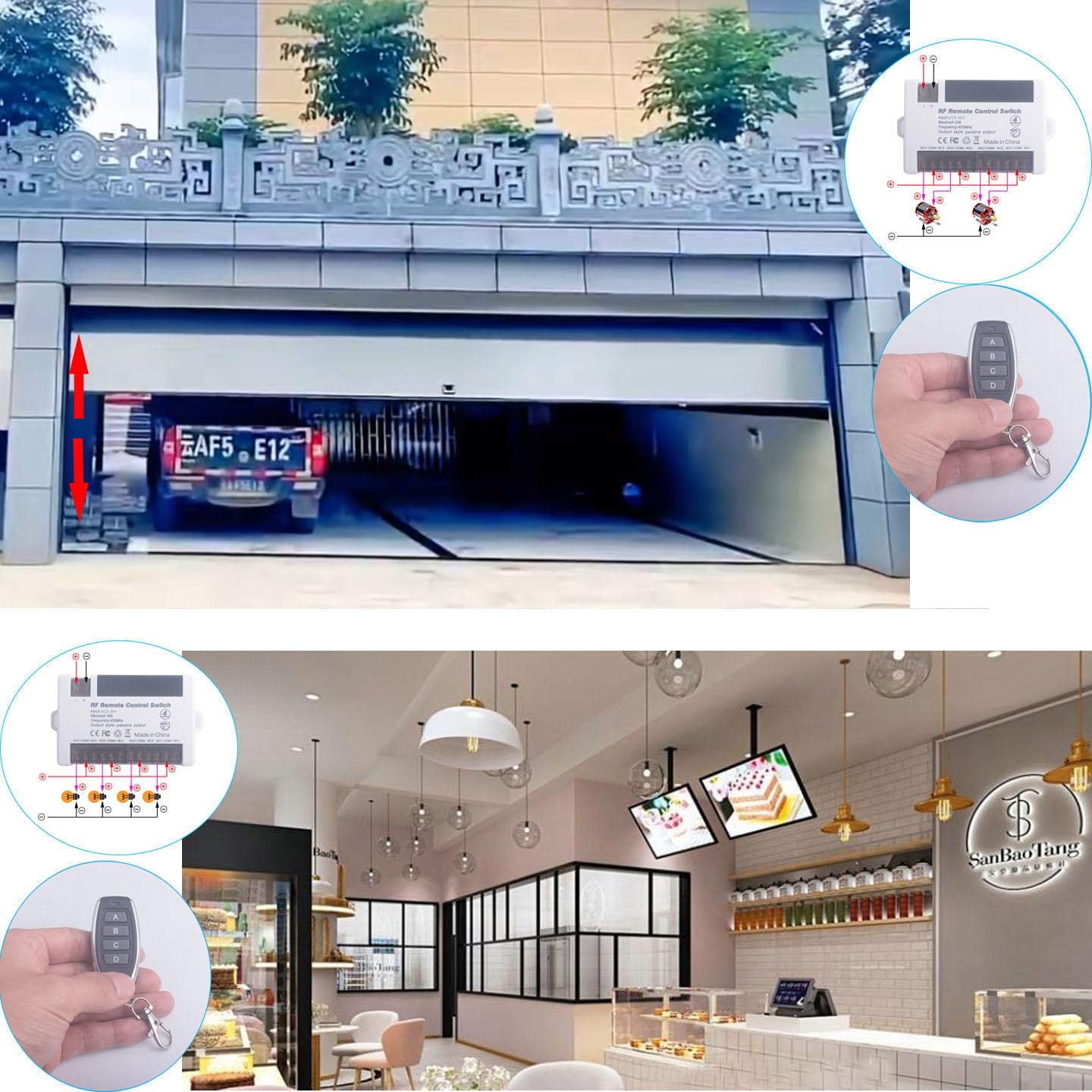
The media could not be loaded.OK, this guy works great. However, the directions are a little flaky. That’s why only 4 stars. 5 star operation, but you have to figure out how to use it. Here’s what I figured out.You need a 5-30VDC supply to power the unit itself. Needs nearly nothing for current – about 5ma @12VDC.You can then use to switch DC loads in the same 5-30VDC range, up to 10A on each relay. Or, more useful typically, it can switch AC load, either resistive or motors, from 1-250VAC and up to 10A each again.It comes with a wiring diagram that shows how to wire. Essentially, you put the DC control voltage on the Vin/GND input. Then, you wire your hot wire that is going to supply the load to the COM terminal for whichever relay will be controlled. Then, you can use the NO (normally open) or NC (normally closed) terminal to wire the hot input wire to the load. Basically, you break into the line voltage going to the load and wire the relay in as a switch in front of the load. The diagram shows how to use for both 2 and 3-channel motor control.The controller allows you to set the relay for different modes. They are momentary (only on while you keep the button pressed on the remote), Toggle (most likely the one you want – one click turns on the device, the next turns it off), or latching/interlock (press button and it cycles through the relays – only one is on at a time).There are also two hybrid modes – one lets you set relay 1 and 2 in momentary, while relay 3-4 are in toggle. The other hybrid mode sets relay 1 and 2 in momentary, while relay 3 and 4 are set to cycle. Those are probably pretty rare use cases, but nice that you have the option.Tips:- The amber windows covering the screw terminals flip up for access. They are HARD to get moving, but just keep prying – they do actually pivot up. It will feel like you are about to break, but they don’t.- Unit comes set for momentary. This may be confusing, since it doesn’t keep the device on as you test.- Directions for setting mode are written poorly. There is a small flip-up window at the top of the unit. Inside, there is a small button. You press the button once to set in momentary mode, then press the A button on the remote to lock in that choice. It says “while pressing control button 1”. More correctly, it should have said “then press control button A”. But the instructions are otherwise correct. Press the button on the board twice to set toggle mode, 3 times for cycling, and 4 or 5 times for the hybrid modes. Just press the A button on the remote to lock it in.- There are also 5 LEDs under the flip-up hood. The first one (closest to the VIN/GND power input) lights only while ANY of the remote buttons are actually being pressed. Lets you know the unit is communicating with remote. The next 4 are lights to show if a relay is actually closed (on) at that time. Light on=circuit on.- The relays are labeled backward. Relay 4 is button A on the remote! Relay 3=B, Relay 2=C and Relay 1=remote button D. Go figure. But this will screw you up, thinking the unit isn’t working.- Based on the backward labeling, the hybrid modes are likewise backward. Mode 4 (momentary and toggle) makes buttons A/B (but relays 3-4) momentary, and buttons C/D (but relays 1-2) cycle. Again, screwy directions.
14 day returns guarantee
Related products
-
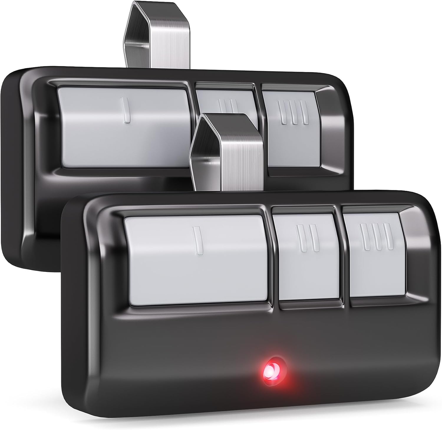 2 for Chamberlain LiftMaster Craftsman Garage Door Opener Remote 893LM 893MAX 971LM Universal with Extra BatteryAdd to cart
-
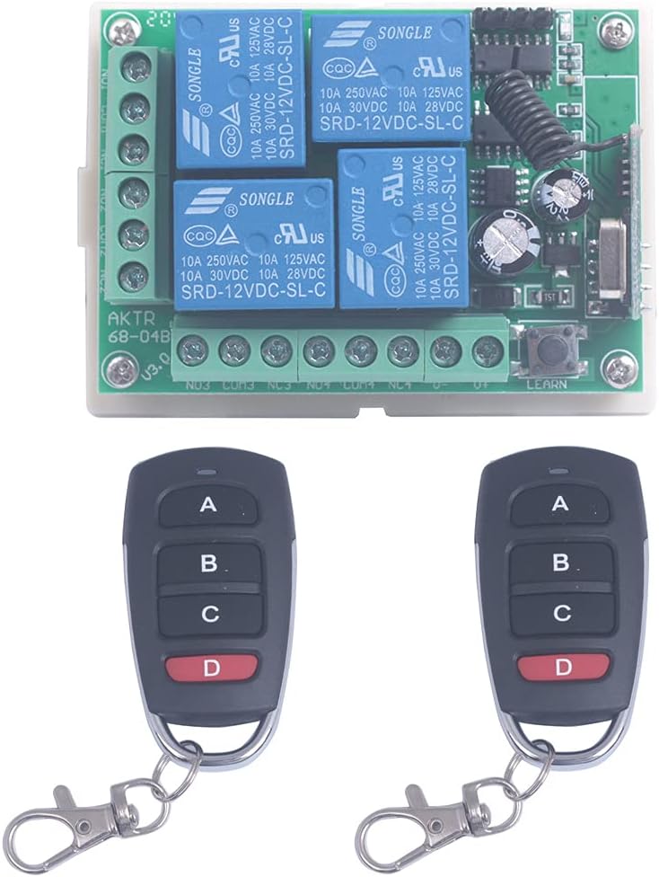 12V 4 Channel Wireless Remote Control Switch Transmitter Receiver Momentary Toggle Switch Garage Door Motor Window Openr Parts (2X Control 315Mhz)Add to cart
-
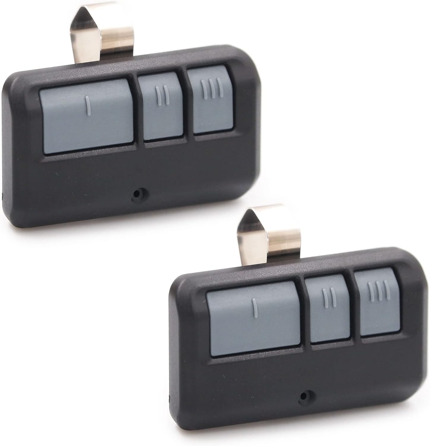 2 for Chamberlain Liftmaster Craftsman Garage Door Opener Remote 893LM 893MaxAdd to cart
-
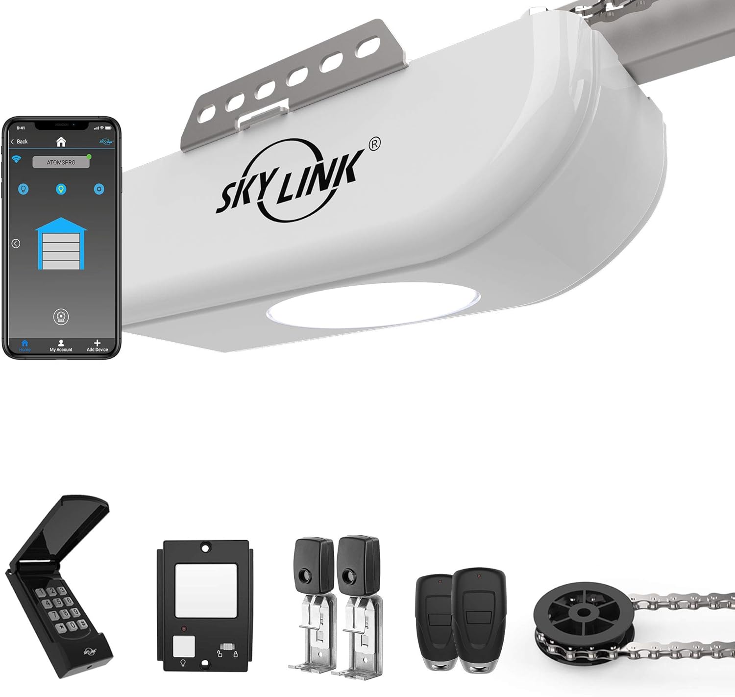 1/2 HPF Garage Door Opener Featuring Alexa with Extremely Quiet DC Motor, Chain Drive, Built-in LED Light, Remote Controls, Deluxe Wall Console, Wireless Keypad and WiFi Compatible, ATR-1622CKWAdd to cart